
How to add own building geometries to a scenario: import of manually created shapefile
Author - Anastasiya Popova

The City Energy Analyst (CEA) requires geometry input in the form of a shapefile (.shp). This article explains how to add your own building geometries to a scenario using the “Import input files” feature in CEA Dashboard.
I am going to show you how to create shapefiles that are supported by CEA with the help of QGIS. QGIS is a free and open-source geographic information system. The version demonstrated below is 3.10.11.
Creating geometries in QGIS

Step2.
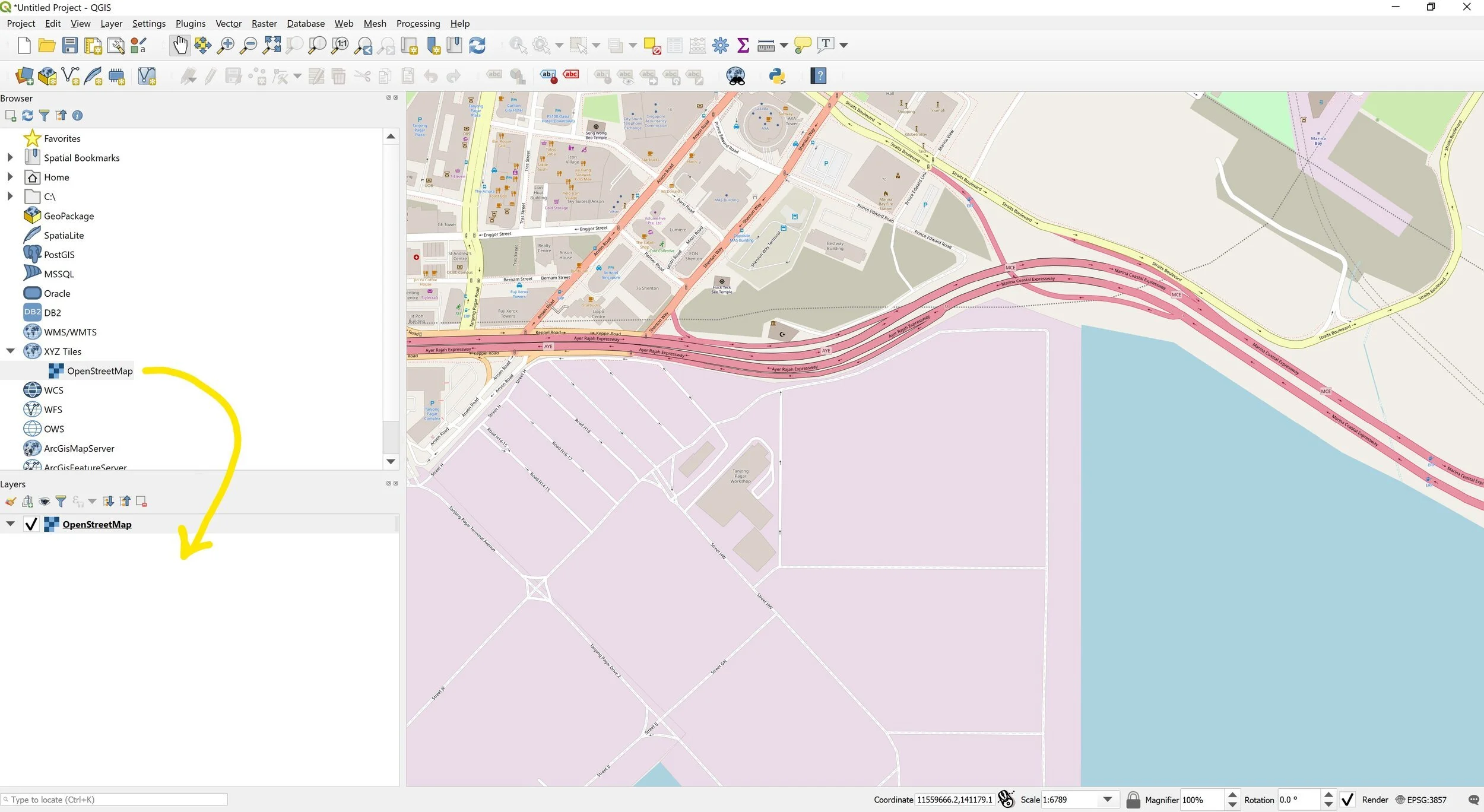
Drag OpenStreetMap into Layers, so that you are able to locate your geometries on the map. Zoom into the needed location on the map.
Step 3.
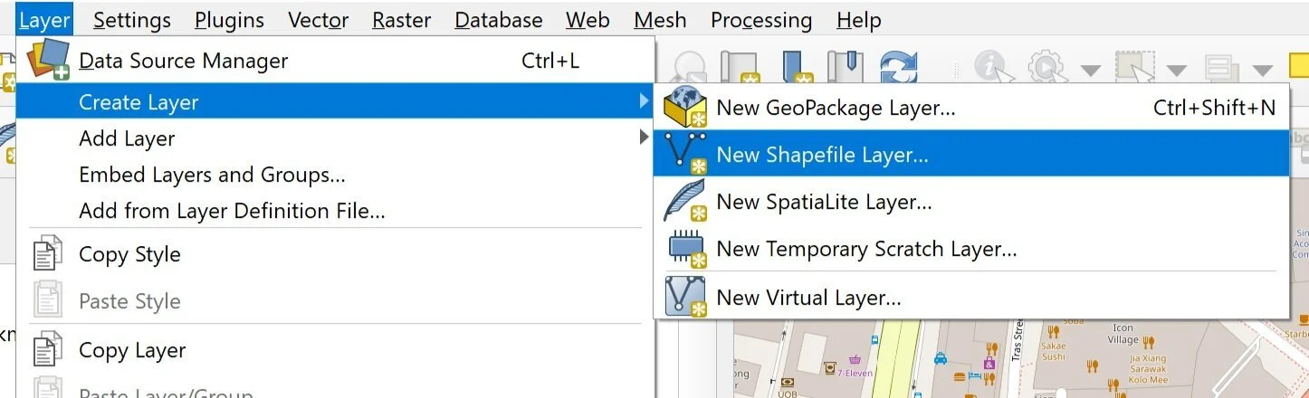
Create new shapefile layer (Layer -> Create Layer -> New Shapefile Layer).
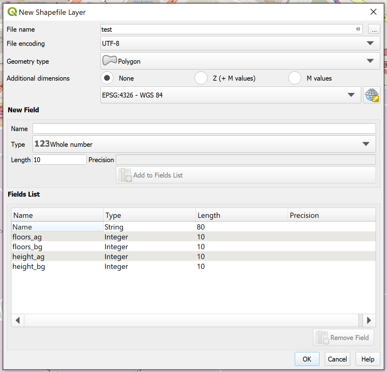
The shapefile must be configured in the following way:
Change geometry type to Polygon.
Set coordinate reference system to WGS 84.
Remove the default “id” field and create new fields, strictly following the upper- and lowercasing of field names:
Name: Name, Type: Text data, Length: 80
Name: floors_ag, Type: Whole number, Length: 10
Name: floors_bg, Type: Whole number, Length: 10
Name: height_ag, Type: Whole number, Length: 10
Name: height_bg, Type: Whole number, Length: 10
Click OK to save the layer.
Note the meaning of the parameters:
Name: Building name
floors_ag: number of floors located above ground level
floors_bg: number of floors located below ground level
height_ag: total building height above ground level
height_bg: total building height below ground level

Step 4.
After saving the layer, right click on the created layer (find it in the bottom left-hand corner “Layers”) and select “Toggle Editing” mode.
Step 5.
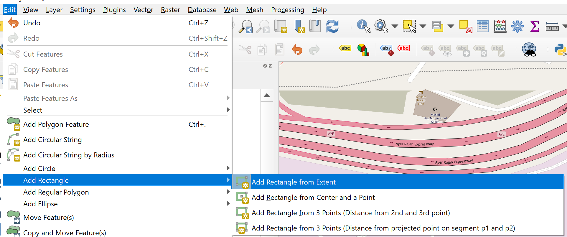
To start sketching your building footprints, select, for example, the “Add Polygon Feature” or “Add Rectangle” (you can repeat this step for multiple geometries).
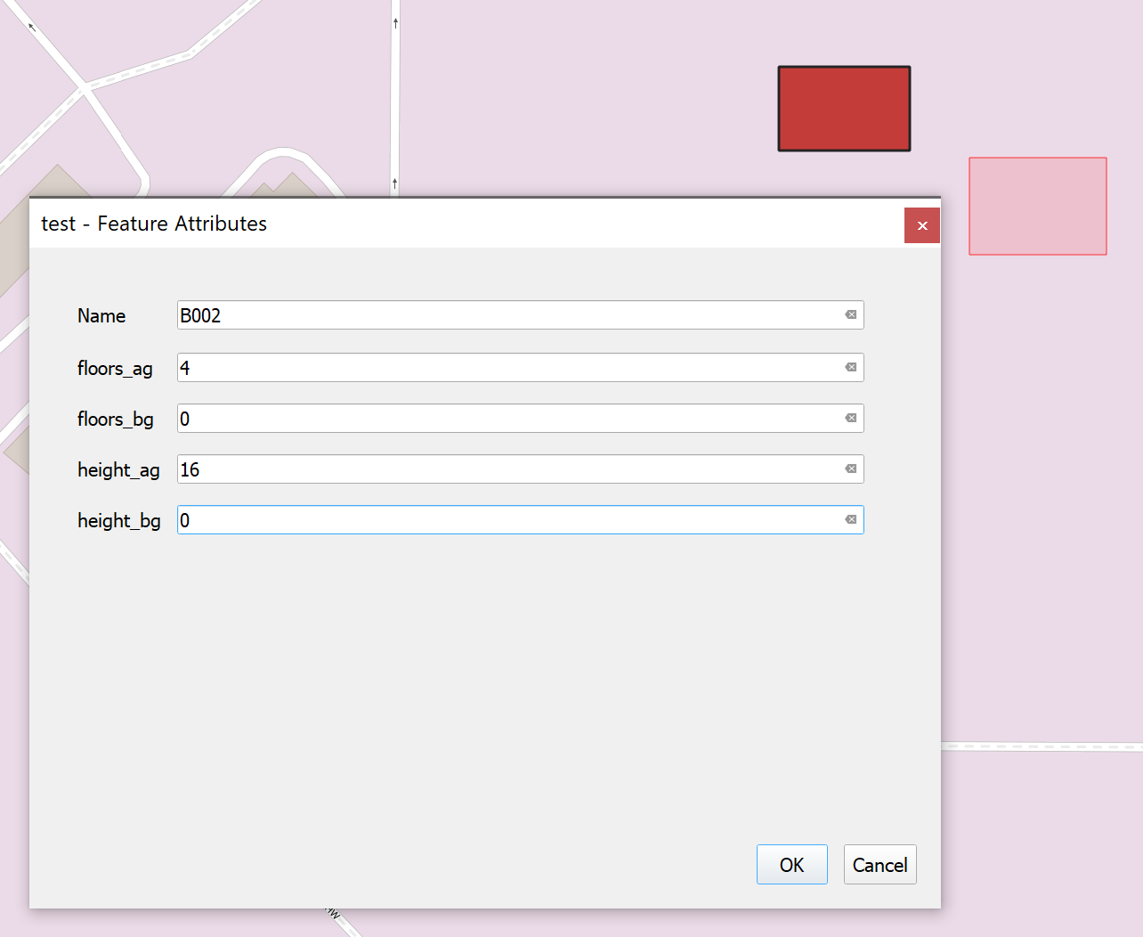
Once you finish drawing the geometry, a window with the parameters created in Step 3 will pop up. Fill them out for each created building and click “OK”.

Step 6.
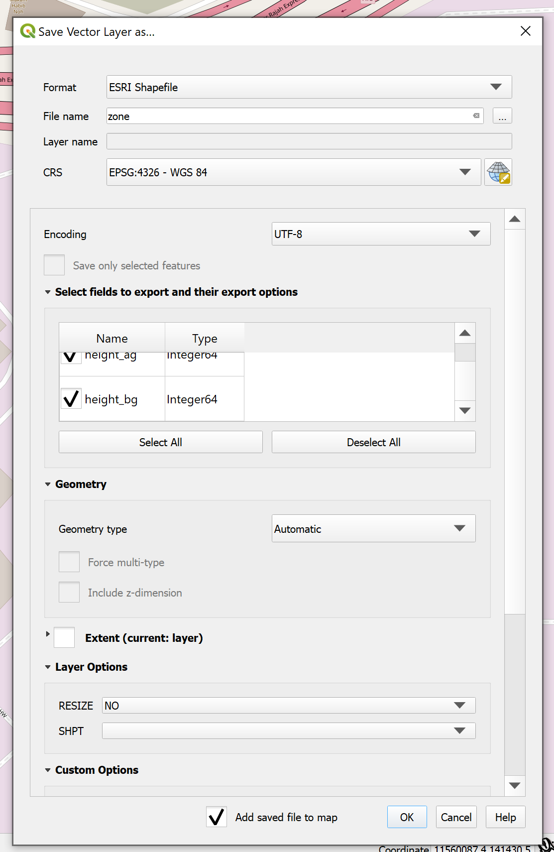
Exit from “Toggle Editing” mode in the same way as described in Step 4. Next, right click on the layer and go to “Export”, “Save Features As…”.
Set the “File name” property to “zone”, and choose a desired file location (keeping all other settings as their default values). Alternatively, if the created building geometries are intended for use as surrounding geometries, the “File name” property should be set to “surroundings”.
Step 7.
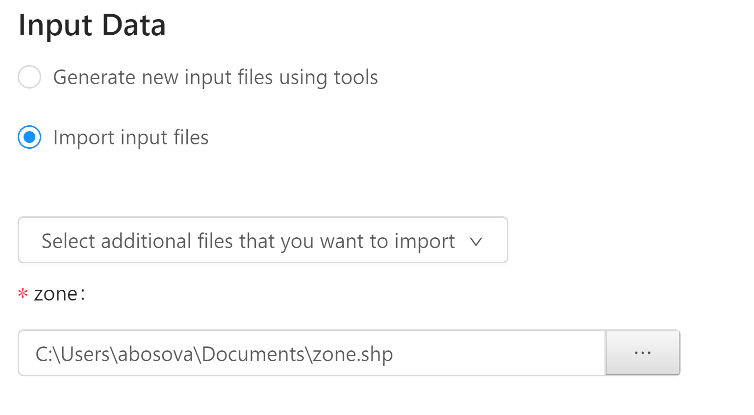
Import created shapefile into CEA using the CEA Dashboard.
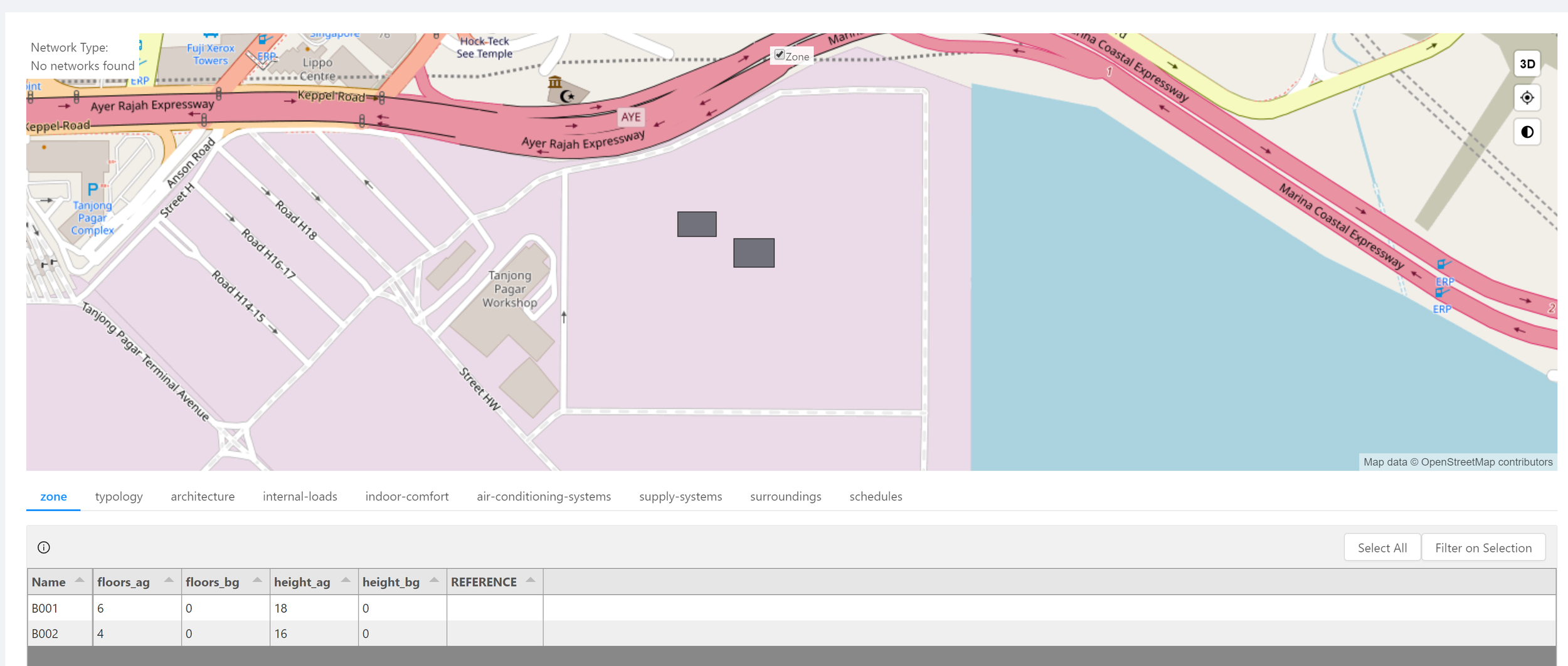
If you can see your geometries on the map as well as the list of buildings with the parameters, your import was successful!
The same workflow applies for geometries created in ArcGIS. Regardless of the tool used, the crucial points are setting the correct coordinate system (WGS 84) and defining the appropriate field names (as defined in Step 3). If the shapefiles were created with the wrong column names, the following Python script can be used to fix it:
from geopandas import GeoDataFrame as gdf

path_to_zone_shp = r"C:\Users\me\Downloads\zone.shp"

zone_gdf = gdf.from_file(path_to_zone_shp)

zone_gdf.columns = ["Name", "floors_ag", "floors_bg", "height_ag", "height_bg", "geometry"]

zone_gdf.to_file(path_to_zone_shp)
NOTE: it is a good idea to do this in an ipython shell, which can be started from the CEA Console. First, check the columns of zone_gdf with zone_gdf.columns - they should be in the same order as the assignment afterwards.
Creating geometries in Rhinoceros and setting building location in QGIS
In case your building geometries were previously created in Rhinoceros, this post will explain how to export geometries to shapefile using the Grasshopper plug-in GhPython. If you are using this workflow, you can enrich created in the Grasshopper shapefile with the correct coordinate system (WGS 84) using QGIS. This will also allow you to place the building geometries in the location of interest. Simply follow Step 1 and Step 2 from above, and drag the exported Grasshopper zone.shp file directly from Windows Explorer into the Layers browser in QGIS.
The “Zoom to Layer” feature will help you to find your geometries on the map. In order to re-locate them, switch to “Toggle Editing” mode.

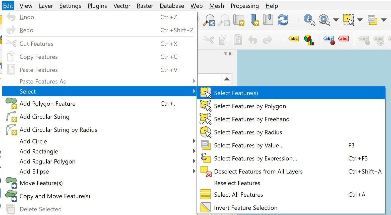
Next, click “Select Features by Polygon” and mark the building geometries on the map.
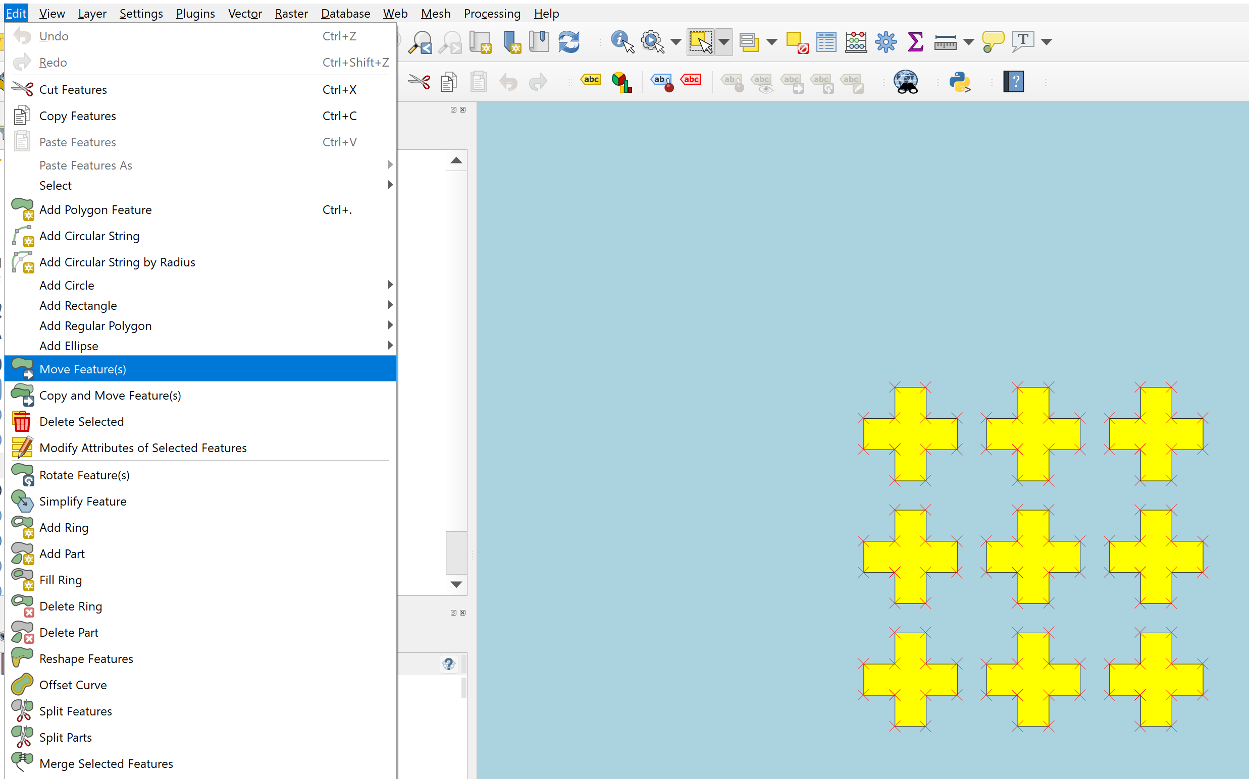
Now you can move them to a specific location by enabling “Move Feature(s)” function and dragging selected geometries.
Once the geometries are located in the proper place, exit “Toggle Editing” mode and go to Step 6 to export them.
Note
Once the new geometries are added to the zone.shp file, the typology.dbf file should be updated accordingly. These two files should contain the same amount of buildings. Here is an example code on how to modify typology.dbf via jupyter notebook with built-in CEA functions.
I hope this information will help you to create a scenario in CEA with your own geometries. Feel free to ask questions in the comment section below and good luck!